Technical role and source
This drawing was prepared by ERGUN G., AKSVERO’s founding technical specialist, as part of his earlier professional work. Authorship was confirmed by the site owner. The displayed source has its title block removed; the original project is not presented as a new commission delivered under the AKSVERO brand.
The technical documentation need
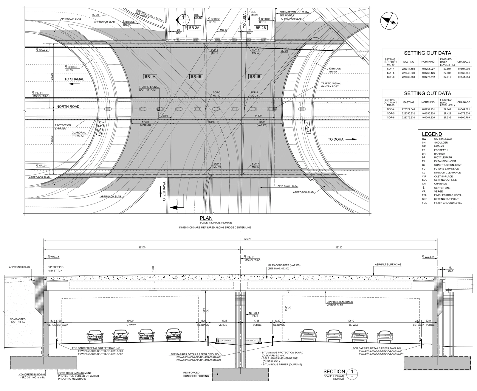
Where several bridge regions and road directions meet, structural locations need to be communicated against the road’s geometric references. The general arrangement establishes this shared location information before readers proceed to detail drawings.
Read the evidence on the drawing
| Focus | Visible evidence | Reading approach |
|---|---|---|
| Plan arrangement | BR1A, BR1E and BR1B regions and bridge centerlines are identified. | Read the structural arrangement, approaches and road lines together. |
| Setting out | SETTING OUT DATA tables contain easting, northing, road level and chainage. | Match point codes to plan locations and confirm the coordinate system separately. |
| Vertical relationship | The section shows deck, piers, foundations and road clearance relationships. | Trace the same elements between plan and section. |
| Local interfaces | Approach slab, joint and barrier references are provided. | Follow the arrangement references to their related detail sheets. |
Documented output
The sheet combines plan, setting-out tables and a vertical section within a shared reference system. This page does not claim that field setting out was performed or that road geometry was recalculated.
A comparable assignment
For a comparable package, first identify the governing design, current drawings, expected file formats and approval responsibilities. Missing information becomes a technical query. The final scope may include model production, drawings and schedules as agreed; the public PDF alone does not establish that all these formats were delivered in the original assignment.