Technical role and source
This drawing was prepared by ERGUN G., AKSVERO’s founding technical specialist, as part of his earlier professional work. Authorship was confirmed by the site owner. The displayed source has its title block removed; the original project is not presented as a new commission delivered under the AKSVERO brand.
The technical documentation need
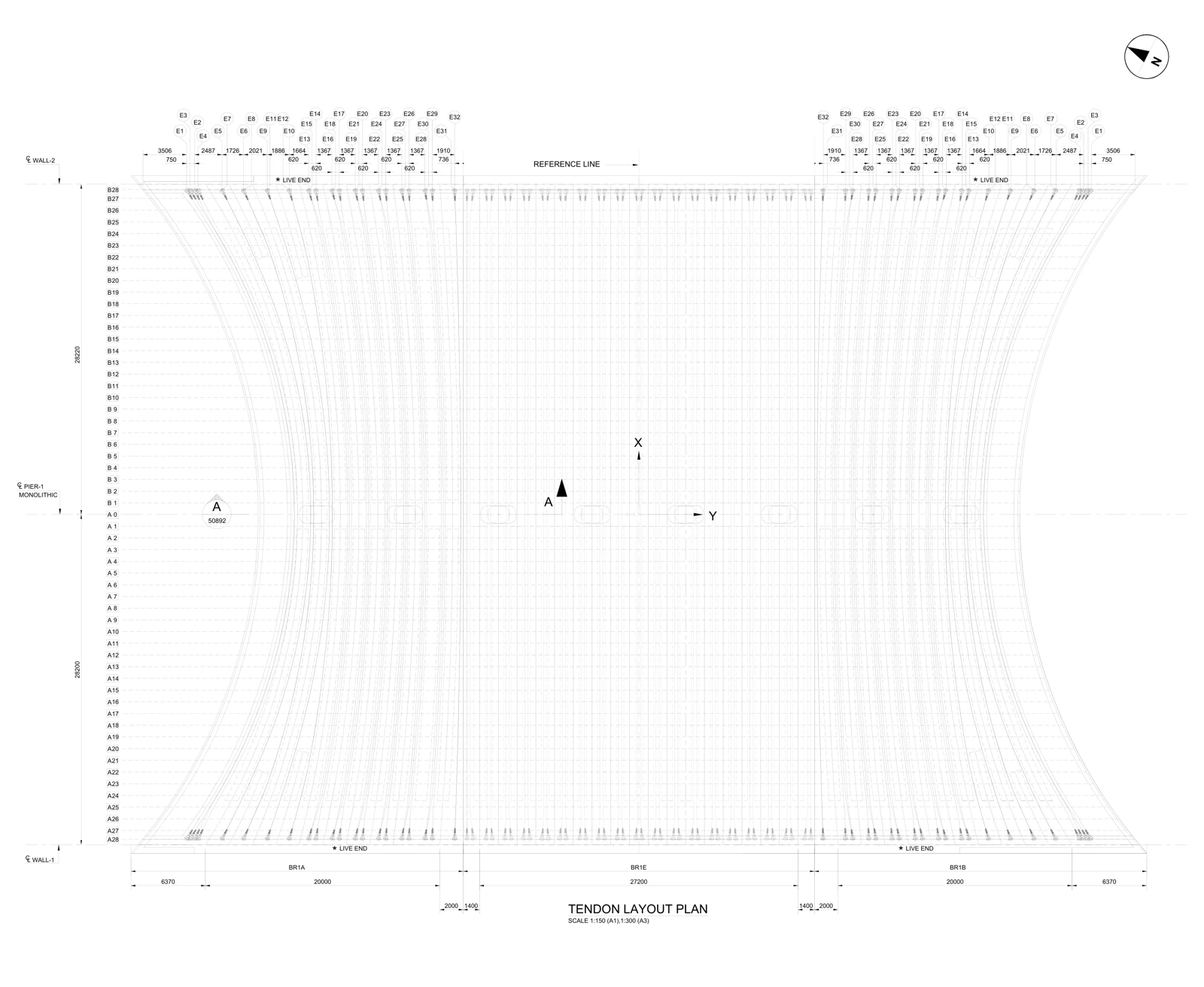
The drawing addresses the documentation of changing tendon paths in relation to end zones and reference lines. In a dense plan, each path needs an identifiable reference as well as a geometric representation.
Read the evidence on the drawing
| Focus | Visible evidence | Reading approach |
|---|---|---|
| Tendon identifiers | E1–E32 labels appear along the upper edge. | Trace identifiers to their paths and end zones. |
| Reference lines | A REFERENCE LINE and pier reference are shown. | Read positions against the stated references, not only the outside drawing edge. |
| End zones | LIVE END notes appear at upper and lower ends. | Stressing direction, sequence and force need the relevant design and procedure documents. |
| Geometry | BR1A, BR1E and BR1B regions share the plan with changing paths. | Trace direction and layout relationships at region boundaries. |
Documented output
The exhibited deliverable is a real layout sheet combining tendon paths, identifiers, dimension chains and references. It is not, by itself, a stressing-force calculation, stressing sequence or field stressing record.
A comparable assignment
For a comparable package, first identify the governing design, current drawings, expected file formats and approval responsibilities. Missing information becomes a technical query. The final scope may include model production, drawings and schedules as agreed; the public PDF alone does not establish that all these formats were delivered in the original assignment.