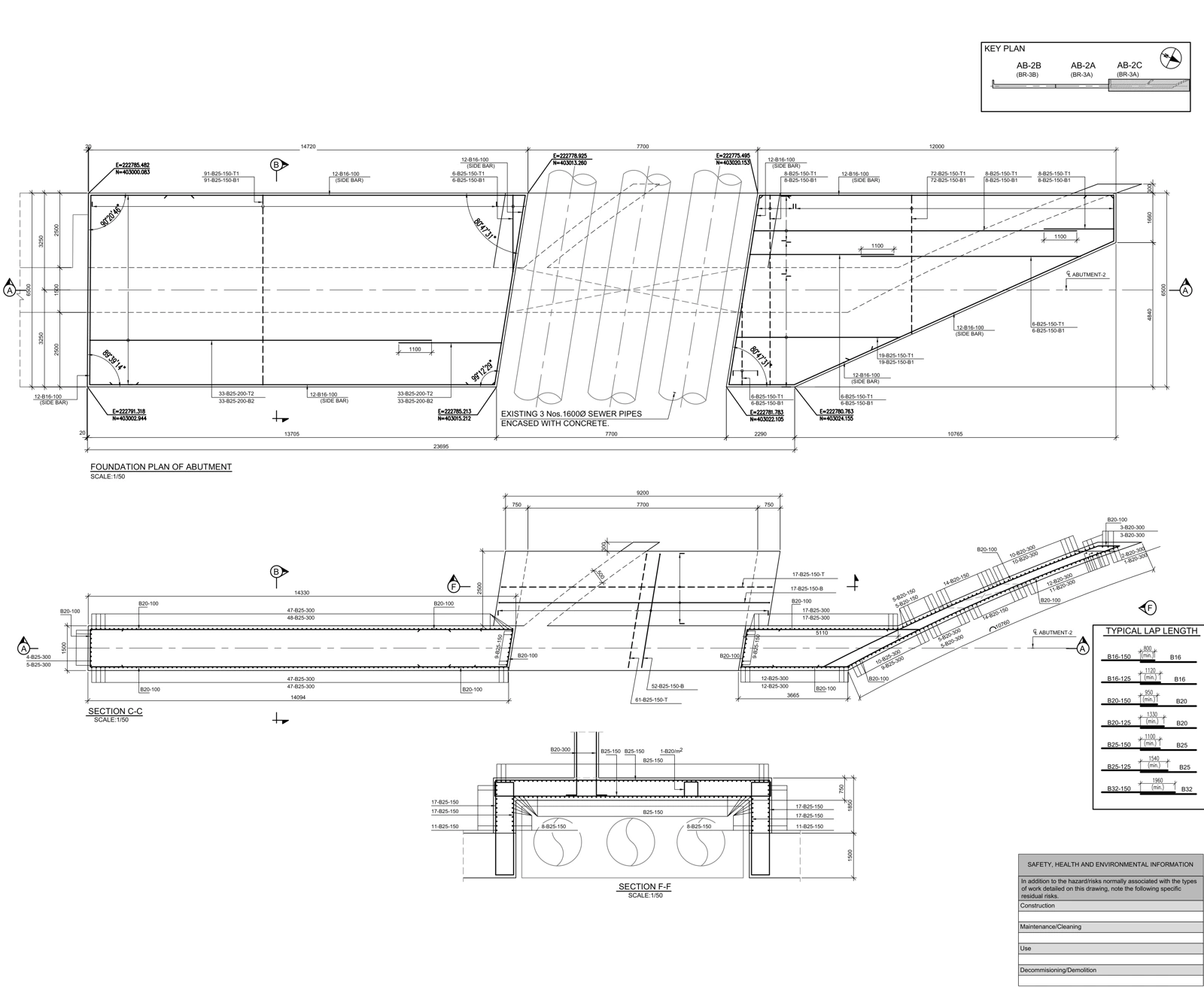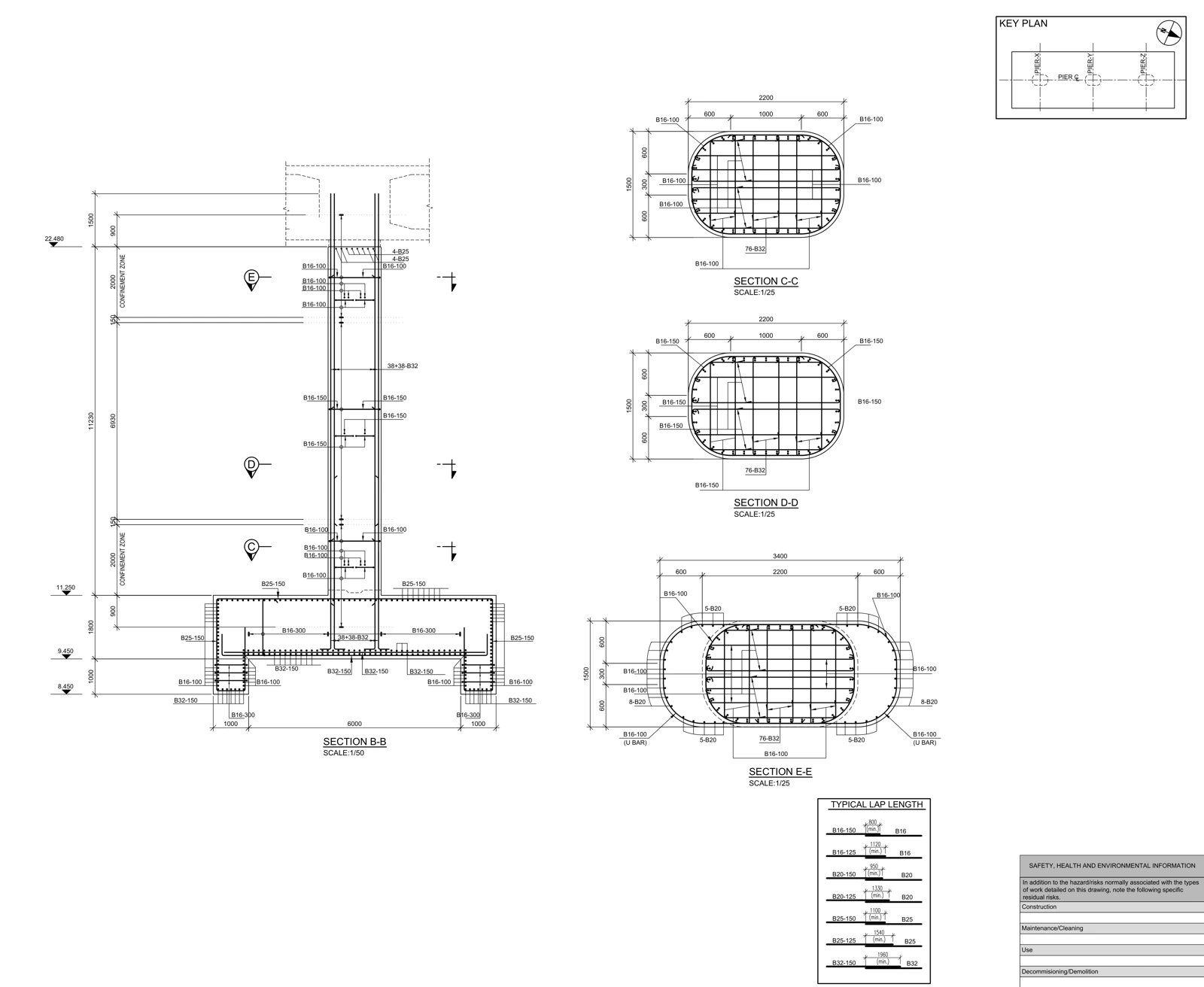
Review the bearing and plinth together with jacking locations, restraints, backwall, drainage and access openings. Separate what the drawing establishes from what requires supplier details or temporary-condition design inputs.
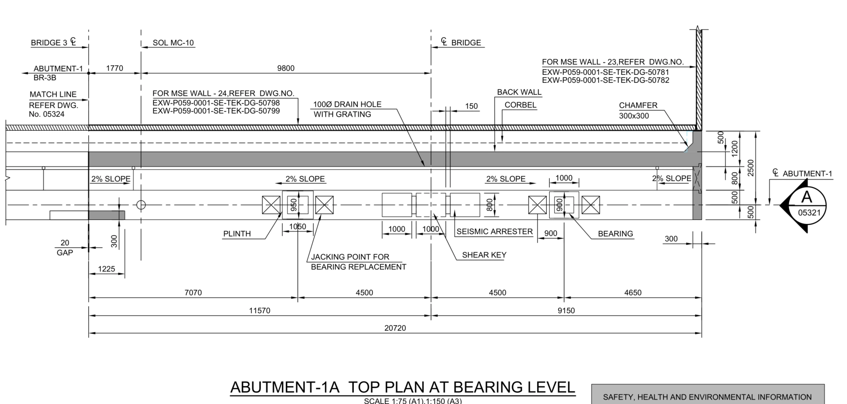
Read the real drawing as a connected evidence set
The selected abutment drawing in our showroom is a real work sample with its title block removed. The elevation, bearing-level plan and sections describe the same element from different directions. Start by matching their references and element identity. A single cropped view cannot establish every interface.
This article does not report a defect in that project. It demonstrates the questions a technical reviewer can derive from the available evidence. Client identity, project location and structural calculation results are not disclosed here.
Trace the level relationship
Follow the relationship between deck, bearing faces, plinth and abutment geometry. Different views may name related surfaces differently. Establish the reference datum and the exact point being described before comparing elevations.
Where seating surfaces slope or plinth heights vary, one elevation may be insufficient. A useful coordination section shows the relevant axis, level and surrounding constraints together. Changing an approved dimension to make the model easier to build is not a substitute for resolving a design query.
Related workflow: Structural revisions: trace a changed detail through every deliverable ↗
Review replacement access as a geometric problem
| Interface | Review question | Additional input |
|---|---|---|
| Bearing / plinth | Does the supplier geometry match the seating surface? | Bearing shop drawing |
| Jacking location | Is there access for placement and lifting? | Equipment envelope and approved method |
| Shear key / restraint | Does it obstruct removal? | Maintenance section and sequence |
| Backwall / opening | Is the approach route defined? | Access detail |
| Temporary load path | Who owns the lifting-condition design? | Authorized design inputs |
Jack capacity, lifting sequence and local concrete effects cannot be verified from a formwork drawing alone. The geometric review identifies where those inputs are required. Florida DOT’s maintenance training treats bearing replacement and jacking as specific maintenance operations; a project still needs its own approved procedure. Florida DOT — Bridge Maintenance Course Series, Appendix A ↗
Follow drainage beyond the symbol
Trace the inlet, route, fall, discharge and maintenance access. A pipe drawn in an elevation does not prove a continuous drainage path. The section levels, plan route and local penetration detail should describe the same installation.
Consider the outlet’s relationship to bearings, joints and access routes. Reinforcement and waterproofing around penetrations may be documented separately. If the relevant detail is missing, state which document and decision are needed. Cutting an opening into a presentation model does not resolve that interface.
Explore the source document: Real drawing study: bridge abutment formwork ↗
Deliver a review that others can act on
- Numbered review locations on the source plan.
- A plan-to-section relationship for each critical interface.
- Separate fields for observed evidence, open question and missing input.
- Questions assigned to the relevant supplier, designer or construction team.
- A list of drawings and model areas affected by the response.
A strong review does not claim to answer every question from one sheet. It puts the right geometry and evidence in front of the person responsible for the decision. Construction issue status belongs to the project’s review and approval process.
Frequently asked questions
Can a formwork drawing prove safe bearing replacement?
No. It supports geometric review, but equipment, lifting procedures and temporary-condition design inputs are also required.
Can the formwork drawing define the reinforcement model?
It can inform concrete geometry. Reinforcement requires the corresponding reinforcement drawings, sections and approved design information for that element.
References and scope
Primary references for software behavior and information-exchange concepts are listed below. Review matrices are workflow examples prepared for AKSVERO. This article is not a project-specific design calculation or construction approval.
Founding technical specialist · Technical drafter · 40 years of industry experience.
Explore the expertise profile ↗