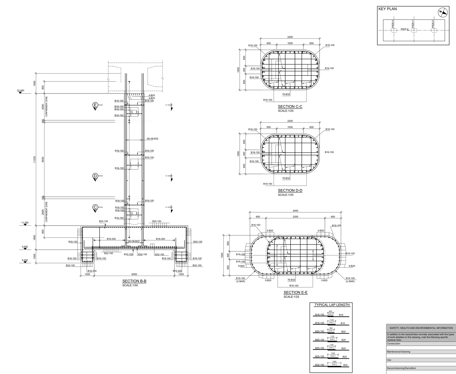
Technical role and source
This drawing was prepared by ERGUN G., AKSVERO’s founding technical specialist, as part of his earlier professional work. Authorship was confirmed by the site owner. The displayed source has its title block removed; the original project is not presented as a new commission delivered under the AKSVERO brand.
The technical documentation need
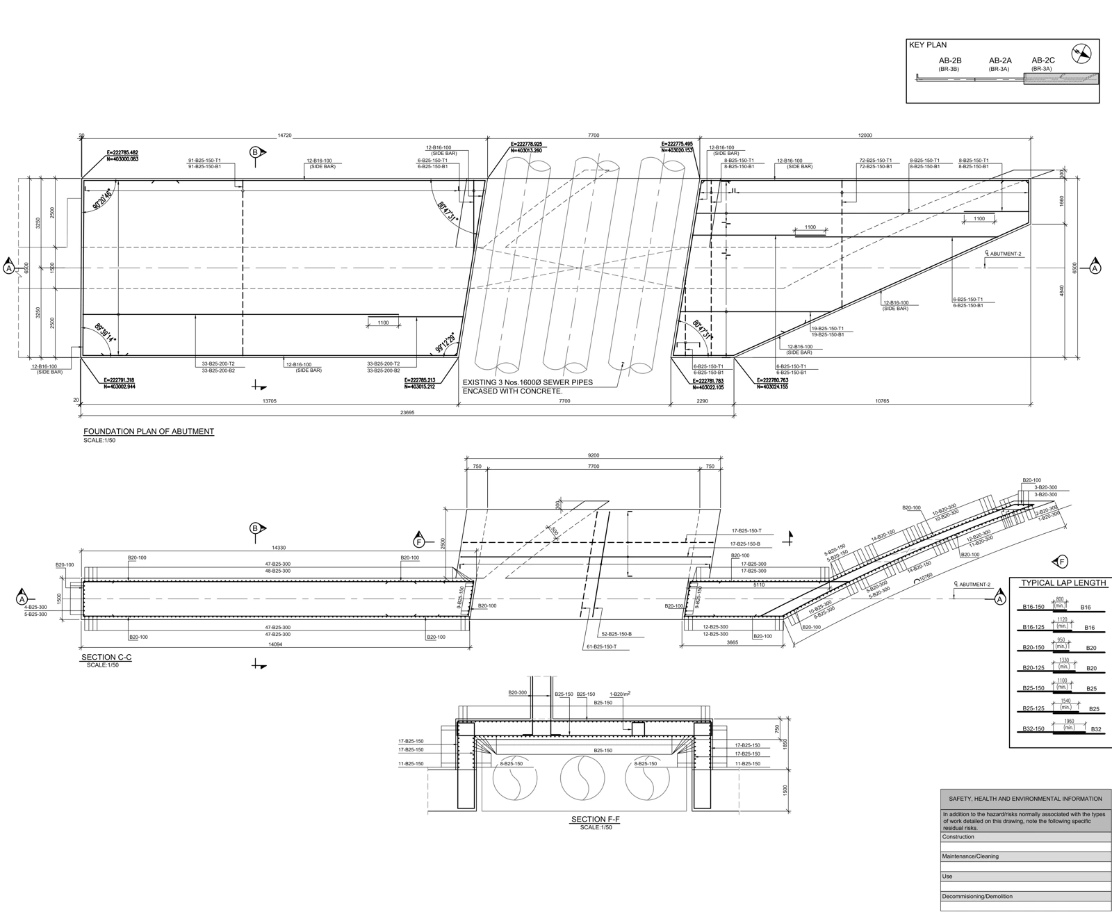
Changing foundation directions and existing pipes make the reinforcement difficult to interpret from a plan alone. Layer notes and sections C–C and F–F provide complementary views of the reinforcement and utility interface.
Read the evidence on the drawing
| Focus | Visible evidence | Reading approach |
|---|---|---|
| Reinforcement layers | T1/B1 and T2/B2 labels appear with diameter/spacing notes. | Trace upper/lower layers and directions against the drawing legend and sections. |
| Foundation geometry | Direction and level changes appear in the plan outline and C–C section. | A straight plan distance is not automatically a developed bar length. |
| Pipe interface | Three existing pipes are shown; section F–F opens this region. | Read reinforcement relationships to openings and surrounding concrete in section. |
| Lap notes | A TYPICAL LAP LENGTH table is included. | Do not transfer this project’s notes to other projects as a universal design rule. |
Documented output
The exhibited deliverable is a plan-and-section sheet connecting reinforcement to foundation geometry and the pipe interface. Full quantity reconciliation requires the corresponding bar schedule and current source set; this presentation is not a numerical checking report.
A comparable assignment
For a comparable package, first identify the governing design, current drawings, expected file formats and approval responsibilities. Missing information becomes a technical query. The final scope may include model production, drawings and schedules as agreed; the public PDF alone does not establish that all these formats were delivered in the original assignment.