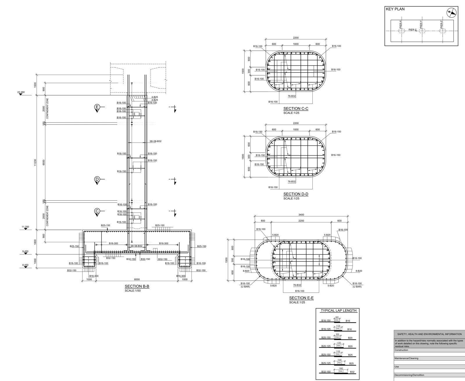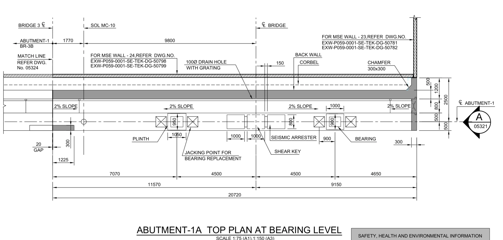
To reconcile a rebar drawing with a bar schedule, align the drawing revisions and element scope first. Check diameter, count and individual length separately, then reconcile total length. Record unresolved boundaries or missing shape information as queries rather than assumed quantities.
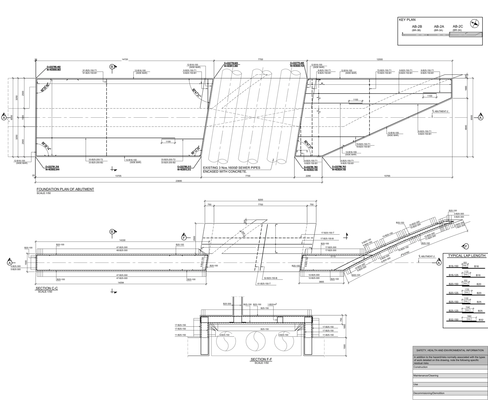
Freeze the scope before checking quantities
A bar mark appearing in both a plan and a section does not necessarily represent two sets of bars. The views may describe the same physical reinforcement. Conversely, a typical detail applied to several foundations may list quantities for one foundation only. Record the element reference, drawing revision, layer, direction and repetition multiplier together.
The review package needs concrete geometry, reinforcement layout, relevant sections and the bar schedule. A formwork drawing defines concrete boundaries; it cannot independently establish hooks, laps or a complete cutting length. Where information is missing, identify the unresolved check and the required input. An estimated measurement from a screenshot is not an equivalent substitute.
Build a traceable record for each bar mark
| Check | Evidence | Common ambiguity |
|---|---|---|
| Element and mark | Plan tag and related section | Mark reused in another scope |
| Diameter / material | Rebar callout and schedule row | Diameter inferred from appearance |
| Count / spacing | Distribution limits and repetitions | Two layers treated as one |
| Individual length | Bar shape and dimensions | Rounded and geometric lengths mixed |
| Total length | Verified count × individual length | Missing element multiplier |
“P12 incorrect” is not a useful closeout record. A stronger example reads: “F01 / bottom layer / X direction / P12: drawing interpretation gives 42 bars, schedule gives 40; confirm whether both boundary bars are included.” This is an illustrative issue description, not a reported defect in the real drawings on this website.
Related workflow: Revit rebar delivery: checking the model, drawings and schedules together ↗
The condition behind a spacing-to-count calculation
If the first and last bar centre lines are exactly 3,000 mm apart, at a uniform 150 mm pitch, there are 20 spaces and 21 bars including both ends. That relationship applies to the defined centre-line interval. Dividing the overall concrete dimension by the pitch is a different calculation: cover, end offsets and distribution limits may still be unknown.
Confinement zones introduce another trap. Counting adjacent zones separately can count the shared boundary bar twice. Establish actual bar positions or an explicit ownership rule for that boundary. Variable spacing requires a zone-by-zone interpretation; a single spacing label cannot describe every bar position.
Separate an arithmetic discrepancy from a design decision
| Training example: P12 | Drawing interpretation | Bar schedule |
|---|---|---|
| Count | 42 | 40 |
| Individual length | 6.20 m | 6.20 m |
| Total length | 260.40 m | 248.00 m |
| Difference to resolve | 12.40 m | 2 bars |
This arithmetic example shows the effect of a count mismatch. It is not a reinforcement design or procurement instruction. Possible causes include missing boundary bars, different scope, separately scheduled repetitions or mismatched revisions. Resolve the evidence before authorizing a schedule change.
For cutting lengths, identify the measurement convention used for bends and hooks. Adding outside dimensions is not a universal method for determining the developed length of a bent bar. Where the source is Revit, inspect the relevant rounding settings before comparing the displayed value with geometric length. Autodesk — Reinforcement Rounding ↗
Explore the source document: Real drawing study: bridge pier reinforcement details ↗
Expose differences hidden by schedule presentation
Revit reinforcement numbering operates within partitions. A visible bar number alone is therefore an incomplete audit key; retain the partition and element context. Autodesk — Rebar Numbering for Schedules and Annotation ↗
Filters, phases, included elements and grouped rows can change the apparent relationship between model objects and a printed total. Start with a sufficiently itemized export, then reconcile it to the intended delivery schedule. Retain the extraction settings so a reviewer can reproduce the result after a revision.
Make the review usable by the next person
- Identify the element, bar mark, document revision and section reference.
- Record observed value, expected value, difference and unit.
- Use matching issue numbers on the marked drawing and discrepancy register.
- Assign a response owner and retain the recheck outcome.
ACI’s detailing guidance emphasizes communicating the designer’s intent clearly to those preparing fabrication and placing information. This audit workflow checks consistency of supplied information; it does not establish structural adequacy. ACI PRC-315-18 — Guide to Presenting Reinforcing Steel Design Details (abstract) ↗
Frequently asked questions
Can reinforcement quantities be checked from PDF drawings?
Yes, where readable dimensions, distribution limits, sections and schedules are available for the same revision. Missing shape or boundary information should remain an open query, not be converted into a definitive quantity.
Does matching total tonnage prove the schedule is correct?
No. Excess and shortfall in different marks can cancel out. Reconcile individual marks and element scope before checking the aggregate.
References and scope
Primary references for software behavior and information-exchange concepts are listed below. Review matrices are workflow examples prepared for AKSVERO. This article is not a project-specific design calculation or construction approval.
Founding technical specialist · Technical drafter · 40 years of industry experience.
Explore the expertise profile ↗